
Movement
Full rotation, swing or small angles of movement.
LUBRICATION SYSTEM
Spiral grooves, pockets, cells and holes according to the working movement of the unit.
LUBRICATION SYSTEM
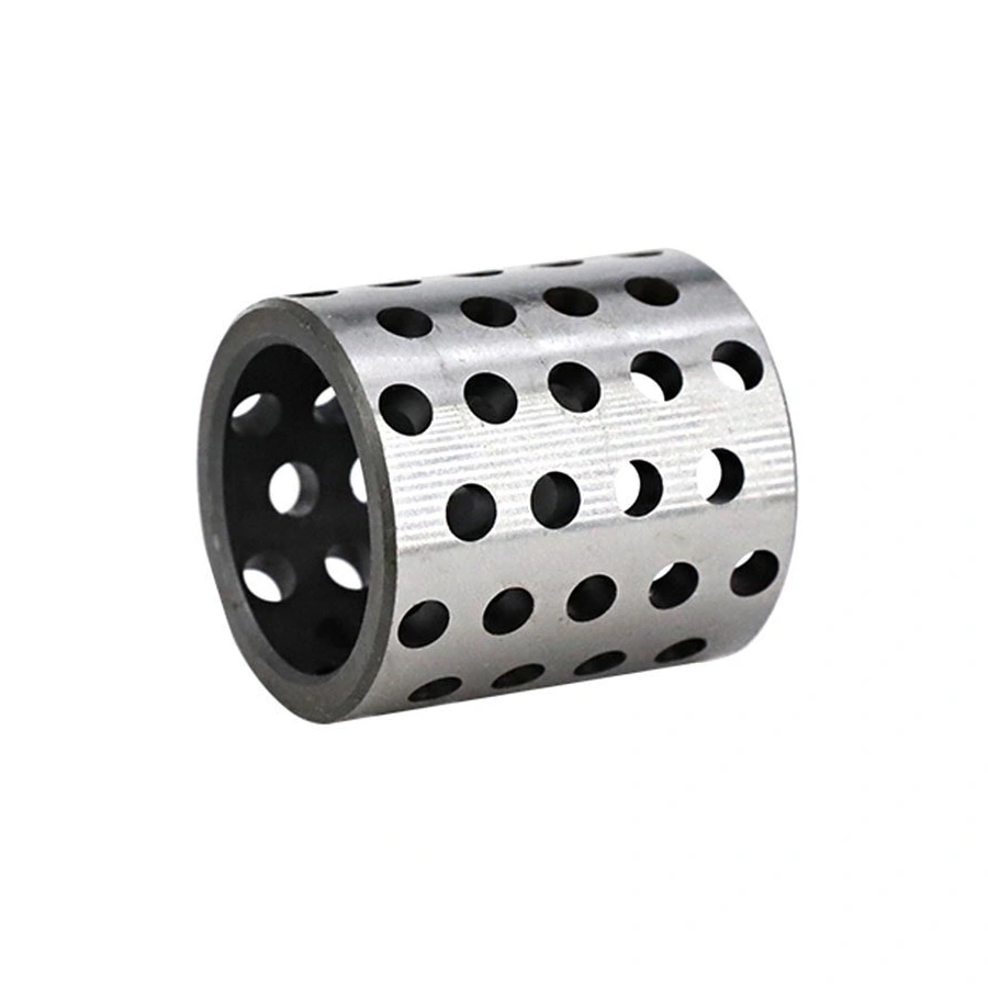
Spiral grooves, pockets, cells and holes serve various functions. Their shape and location are determined taking into account the direction of movement, workload, wall thickness and ease of maintenance.
WHAT TO CHECK
There is no universal pattern for all hinges.
Full rotation, swing or small angles of movement.
Working area and direction of the resulting force.
Permissible groove depth and hole location.
Type of lubricant and frequency of its supply.
HOW THE WORK IS CONSTRUCTED
After checking the drawing, coordinates, transitions and control dimensions are set. Geometry is performed before or after individual routing operations, depending on the material and heat treatment.
Direction of movement and delivery point.
Tool, depth and accessibility of processing.
Position, edge cleanliness and work surface.
RESULT
The shape of the grooves and holes must be recorded in the documentation so that a repeat batch reproduces the same working surface.
BEFORE AGREEMENT
Grooves, pockets, cells and holes perform different functions and are not selected based on the image alone. Coordination requires the direction and amplitude of movement, load zone, lubricant viscosity, supply path and service interval. The wall thickness should allow the selected geometry to be performed without weakening the part.
Rotation, swing, stroke and direction of load change.
Entry point, holes, distribution and outlet of lubricant.
A groove, pocket or cell linked to the working area.
Dimensions of elements, cleanliness of channels and surface condition.
NEXT STEP
The joint section, lubricant type, maintenance frequency, and bushing drawing are helpful.